
You can calibrate the material coefficients, the pathloss formula K1 and K2, and the Clutter loss for outdoor project, including the following variables:
- Transmission. The transmission loss in the selected profile.
- Reflection. The reflection loss in the selected profile.
- Diffraction. The diffraction loss in the selected profile.
- Loss constant. The constant (K1) of the pathloss formula in the selected profile.
- Pathloss exponent. The exponent (K2) of the pathloss formula in the selected profile.
- Clutter loss. The transmission loss of each type of clutter in the selected profile. There is no default clutter database in the material database. The clutter loss is read from the clutter data, which is read from the imported GIS data of a specific project. The clutter transmission loss value is 0 by default.
These values are automatically calibrated using the calibration module. After calibration, the calibrated coefficients can be saved in the selected propagation profiles. The calibrated coefficients will not be saved to the material database or clutter database, but you can save the propagation profile and reuse it in other projects by importing and exporting the propagation profile.
Prerequisites:
- You must have a relevant system in the current project.
- Measurement data for the system must be present in the current project.
- The measurement data must include the following fields: X, Y, Z, Cell_ID, RX_LEVEL.
To calibrate propagation coefficients:
- From the System Explorer Window, right-click the name of the system and band you want to calibrate and select Calibration under Propagation Modelling, as shown in Figure 25-63.
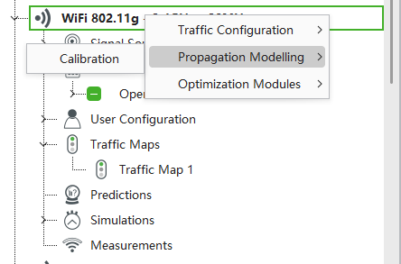
Figure 25-63: Calibration - Under Input in the Calibrate Propagation Model window, configure the following settings:
- Scene. The scene to calibrate, indoor or outdoor, as shown in Figure5.41 and Figure5.42.
- Resolution. The calculation resolution for calibration.
- Select measurements for calibration. The measurement data used in the calibration.
- Measurement point filter. The data pre-processing progress filters out unwanted measurement data.
- Rx Power Range (dBm). Remove the invalid points where Rx power is too large or too small, the valid range depends on the system.
- SINR Range (Db). Remove the invalid points where SINR is too large or too small, the valid range depends on the system.
- Distance Range (m). Remove the invalid points where the distance between the cell sites and the receive points is too far or too near.
- Angle Range (degree). Remove the invalid points that are not in the main lobe angle range of the directional antenna.
- Regression Tolerance (Db). Remove the invalid points that are out of the regression tolerance. The regression is defined by a linear equation or regression function of y = ax + b based on the points set. As there are numerous points, you must calculate the best a and b to minimize the sum of the mod error by excluding the data points that are exceeding the thresholds, for example, 20dB.

- Moving average: Remove fast fading in the data, use the Lee sampling method to average the Rx value with 40lamda range.
- Clutter Class Filtering. Clutter loss only exists for outdoor scene calibration.
- Select cells for calibration. Select the cells for calibration.
Figure 25-64 shows the input fields for the indoor calibration model.
 Figure 25-65 shows the input fields for the outdoor calibration model.
 Figure 25-65: Outdoor calibration model input
3. In the Calibration tab, select the propagation model items to calibrate:
- Enable material calibration. Tick to select the material for calibration, set the Minimum and Maximum Reflection, Diffraction and Transmission parameters.
- Enable pathloss calibration. Tick to enable the pathloss Exponent and pathloss Constant for free space propagation equation, set the Minimum and Maximum parameters.
- Enable clutter calibration. Tick to enable the clutter calibration, which is enabled only for the outdoor scene, set the Minimum and Maximum parameters.
Figure 25-66 and Figure 25-67 show indoor and outdoor calibration items.
Figure 25-66 and Figure 25-67 show indoor and outdoor calibration items.
 Figure 25-66: Indoor calibration Items
 Figure 25-67: Outdoor calibration Items
4. When calibration is complete in the Output tab of the Calibration window, check the calibration results before and after calibration, as shown in Figure 25-68 and Figure 25-69 for the indoor and outdoor scenes.
Figure 25-68 shows outdoor scene calibration results. Figure 25-68: Indoor scene calibration results
Figure 25-69 shows outdoor scene calibration results. Figure 25-69: Outdoor scene calibration results
5. In the Chart tab, compare prediction data with measurement data.
6. Tick Prediction Before, Measurement, and Prediction After to compare the measurement and prediction before and after calibration.
7. When calibration is complete, click Commit to apply the material property to the material property database. You can also select Duplicate materials to paste the material property into the newly created material inside the material database.
 Figure 25-70: Chart view of calibration
8. When calibration is complete, click Report to open a new Calibration Report form, which includes General, Calibration Result, Statistic Before Calibration, and Statistic After Calibration. You can export the report to Word, Excel, and PDF format.
 Figure 25-71: Calibration report
For Maxwell propagation engine, Foliage, Body loss zone and Terrain diffraction coefficient (Ktdiff) can be calibrated.
Please note:
- Terrain Diffraction must be ticked in the Maxwell profile configuration to be considered in calibration.
 Figure 25-72: Terrain Diffraction configuration
- Body loss zone calibration items are available for the indoor scene
 Figure 25-73: Body Loss Zone parameters before calibration
 Figure 25-74: Body Loss Zone parameters After calibration
- Foliage and Terrain diffraction calibration items are available for outdoor scene.
 Figure 25-75: Foliage and terrain diffraction parameter before calibration
 Figure 25-76: Foliage and terrain diffraction parameter after calibration